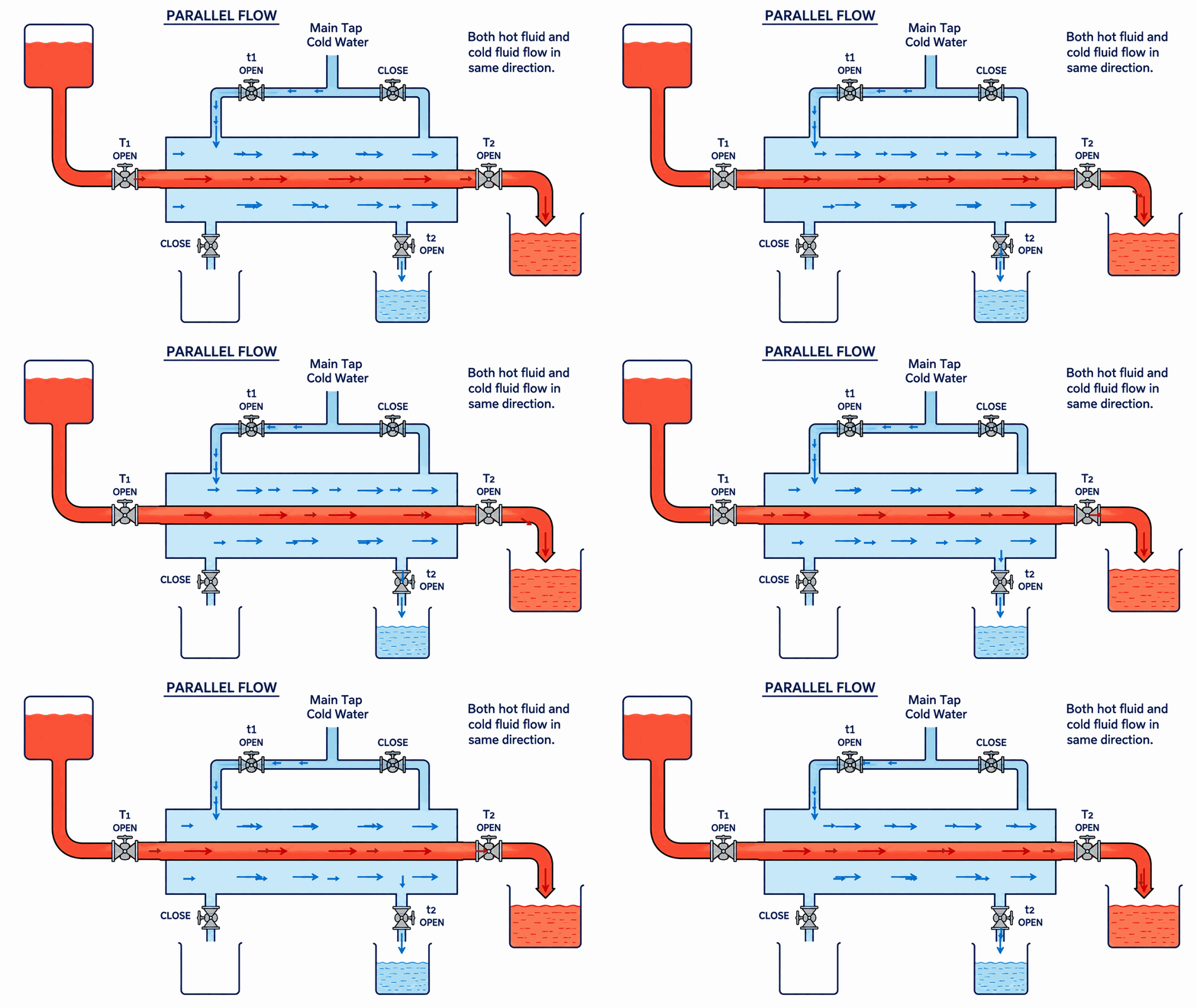
Hot and cold fluids enter at the same end and travel in the same direction. The temperature difference is
greatest at the inlet and decreases along the exchanger.
T1T2t1t2mhmc
Hot fluid Cold fluid
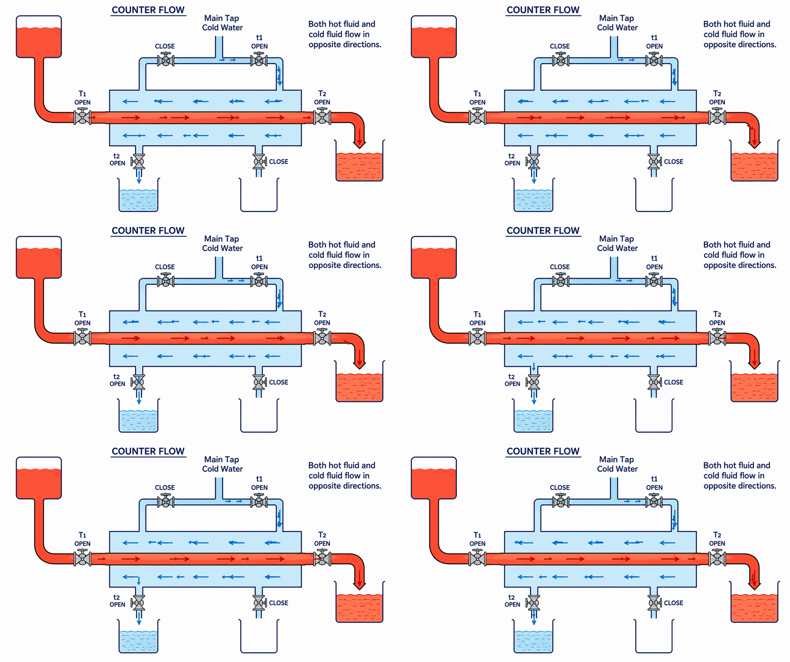
Opposite directions
Counter-flow heat exchanger
Hot and cold fluids enter at opposite ends and travel in opposite directions, maintaining a more uniform
temperature difference along the exchanger.
T1T2t1t2mhmc
Hot fluid Cold fluid
Live calculations
Observation & calculation table
Edit any reading. Calculated values update immediately.
Parallel flowLMTD temperature pairs update
automatically for the selected arrangement.
Heat exchanger observations and calculated performance
Run
Collection time (s)
Mass flow (kg/s)
Temperature (°C)
Heat transfer (W)
LMTD (K)
U (W/m²·K)
Effectiveness
Hot th
Cold tc
mh
mc
T1 Hot in
T2 Hot out
t1 Cold in
t2 Cold out
Qh
Qc
Average heat transfer—watts
Average overall coefficient—W/m²·K
Average effectiveness—dimensionless
Reference
Theory & method
Aim
Conduct heat-transfer tests in parallel- and counter-flow arrangements; determine heat-transfer rate,
overall heat-transfer coefficient, and effectiveness.
Apparatus
Concentric-tube heat exchanger
Measuring flasks
Stopwatch and temperature indicators
Core equations
Mass flow ratesmh = ρV/th = 1/th
kg/s mc = ρV/tc = 1/tc kg/sFor water: ρ =
1000 kg/m³ and V = 1 litre = 0.001 m³, therefore ρV = 1 kg. Standard notation may also be written as
ṁh and ṁc.
Hot-side heat transferQh = mh cp
(T1 − T2)
Cold-side heat transferQc = mc cp
(t2 − t1)
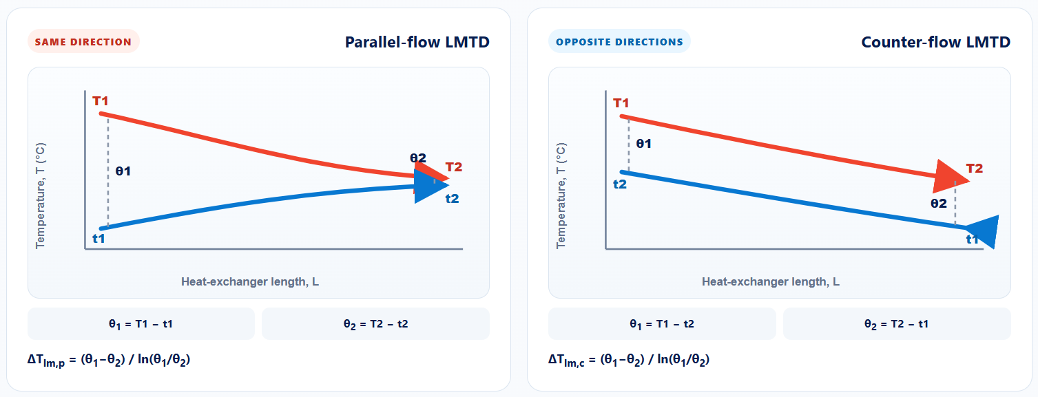
General LMTD equationΔTlm = (θ1 −
θ2) / ln(θ1/θ2)The definitions of θ1 and
θ2 depend on the flow arrangement, as shown below.
Overall coefficientU = Qavg / (A ·
ΔTlm)
Effectivenessε = Qavg / [Cmin(T1 −
t1)]
Procedure
Set valves for the selected flow arrangement.
Switch on the heater and admit cold water.
Adjust hot and cold flow rates to steady values.
Allow temperatures to reach steady state.
Record inlet/outlet temperatures and collection times.
Repeat for several flow rates, then calculate performance.
Parallel-flow and counter-flow temperature profiles and their corresponding LMTD equations.
Arrangement comparison
Characteristic
Parallel flow
Counter flow
Fluid direction
Same direction
Opposite directions
Temperature difference
Falls rapidly along length
More uniform along length
Typical effectiveness
Lower
Higher
Cold outlet limit
Below hot outlet
Can exceed hot outlet
Student assessment
Heat exchanger quiz
Each student receives four questions selected randomly from the complete question bank.
0/ 30 students
4
Four questions · Four marks
Questions may cover parallel flow, counter flow, multiple choice, true or false, and fill in the blank.
COLLEGE OF ENGINEERING & TECHNOLOGYM&I SECTION · HEAT EXCHANGER
QUIZ
Student
0/40%
Maximum marks: 4
Class mark register
Up to 30 completed student reports are retained on this device.

 T1T2t1t2mhmc